A bright idea
A light switch is a simple object: it's either on or off. But this simple binary system is enough to illustrate Boolean algebra, on which all modern computers are based. Yutaka Nishiyama illuminates the connection between light bulbs, logic and binary arithmetic.
Maths in everyday life
Maths is hidden within the simplest things in life, and sometimes you don't even notice it. When you come home at night, for example, and it is dark, you switch on the light in the hall. Later on, when you go upstairs to bed, you switch it off again by another switch on the upstairs landing. But how does the upstairs switch know that the light is on and its job is to switch it off? Does it communicate with the switch downstairs somehow? Is it remote-controlled? The answers to questions like these serve as a good example for the binary system that underlies Boolean logic and the workings of modern computers.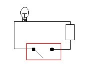
Figure 1: a simple circuit.
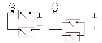
Figure 2: the two circuits.
|
|
|||||||||||||||||||||||||||||||||||||||||||
Mathematical logic and truth tables
These two tables are nothing more than the "truth tables" for the "logical operators" AND and ORfrom mathematical logic. Let's replace the statement "gate 1 is pointing upward" by any other statement P, for example "it is raining", and the statement "gate 2 is pointing upward" by any other statement Q, for example "I am wet". Now the statement P AND Q - "it is raining ANDI am wet" - is true precisely when both P and Q are true. If we write "1" for "the statement is true" and "0" for "the statement is false", then the table below tells us exactly when the statement P AND Q is true for the four different combinations of truth values for P and Q. This table is exactly the same as that for the first circuit, which makes sense, as saying "the light is on" is the same as saying "gate A AND gate B are pointing upward".| AND | ||||
|---|---|---|---|---|
| P | 1 | 1 | 0 | 0 |
| Q | 1 | 0 | 1 | 0 |
| P AND Q | 1 | 0 | 0 | 0 |
The second table corresponds to the OR operator. In mathematical logic, the statement P OR Q is true when one of P or Q is true or when both are true, and false when both are false. This reflects what happens in our second circuit: the light is on if gate 1 is pointing upward or gate 2 is pointing upward or if both are pointing upward. The truth table of the OR operator is exactly the same as the table for the second circuit.
| OR | ||||
|---|---|---|---|---|
| P | 1 | 1 | 0 | 0 |
| Q | 1 | 0 | 1 | 0 |
| P OR Q | 1 | 1 | 1 | 0 |
The simple on/off switch in figure 1 also has its logical meaning: it corresponds to the negating operator NOT. If statement P - "it is raining" - is true then the statement NOT P - "it is not raining" - is false, and vice versa.
The three little words AND, OR and NOT are immensely powerful. They are the basis of mathematical logic, which in turn gives rise to Boolean algebra. Mathematical logic provides a rigorous way to decide whether complicated statements, which often occur in mathematics, are true or false. It is based on the following idea: we have a number of statements, such as "it is raining", which can be either true or false. The operator NOT is used to negate a statement. Using AND and OR we can connect two statements. In this fashion, we can build up long "sentences", for example P AND ((Q AND S) OR NOT (T OR W)), where P,Q,S,T and W are statements. We can figure out whether such a sentence is true by looking at the truth values of the individual statements and consulting the truth tables of AND and OR.
To see why this truth table makes sense, let us first assume that the statement P IMPLIES Q - "if it rains then I get wet" - is true, the situation indicated by a "1" in the last line of the truth table. This could happen, for example, if standing in the middle of a field without any umbrella or other protection. Now if it is indeed raining, then you know immediately that I am wet. Both the statements "it is raining" and "I am wet" are true, and we get the entry "1" for both P and Q in the truth table. If it is not raining, you don't know if I'm wet or not - I might have fallen into a pond and got soaked, or I might be dry. The statement "I am wet" can be either true or false, and this accounts for the last two columns in the truth table. The only remaining possibility is that it is raining but I am not wet. In this case the statement "if it rains then I get wet" is clearly false - I must have brought an umbrella after all. This is the second column of the truth table.
| IMPLIES | ||||
|---|---|---|---|---|
| P | 1 | 1 | 0 | 0 |
| Q | 1 | 0 | 1 | 0 |
| P IMPLIES Q | 1 | 0 | 1 | 1 |
But this truth table is exactly the same as that for the expression NOT P OR Q "it is not raining or I am wet". This makes sense: if P IMPLIES Q is true, then I can replace the statement "it is raining" by "I am wet", as one follows directly from the other. The true statement "it is not raining or it is raining", then becomes "it is not raining or I am wet" - NOT P OR Q is true. If P IMPLIES Q is false, then I may well be dry even though it is raining - the statement "it is not raining or I am wet" is false. We see that P IMPLIES Q is true or false precisely when NOT P OR Q is true or false. The two are equivalent, and we can express the relationship P IMPLIES Q using only the operators NOT and OR.
Boolean Algebra
In the mid-nineteenth century, the English mathematician George Boole invented what is known today as "Boolean algebra". His ingenious idea was to treat the individual statements, like P and Q above, as variables and to define the logical operators as mathematical operations, similar to addition and multiplication. If, for example, we write PQ for P ANDQ and P+Q for P ORQ, then our two circuits above can be expressed by the two equationsLight = A+B.
Dealing with logical statements, simplifying them and finding their truth value, then just turns into manipulation of algebraic expressions, like simplifying or solving an equation. These algebraic manipulations are of course governed by strict rules, and performing them becomes a "mindless" activity - you just follow a set of rules, a machine can do it. Indeed, today, all computers are based on Boolean algebra, another example that mathematics is often a hundred years ahead of its time.
Incidentally, it was Boole's work that inspired the English mathematician John Venn to establish his comprehensive theory of Venn diagrams. Venn diagrams deal with sets, their union and intersection.
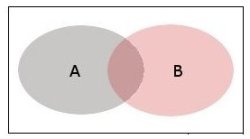
A Venn diagram showing two intersecting sets A and B.
Binary arithmetic
So how do we get logic into a computer? How can we use the ideas set out above to get a computer to perform high-speed, high-precision calculations? A computer operates on six basic electronic circuits: the AND, ORand NOTcircuits described above, the negations of ANDand OR, known as NANDand NOR, and a circuit called XOR, or exclusive OR. XORcorresponds to the logical expression (P ANDNOTQ) OR(NOTP ANDQ), its truth table is given below.| XOR | ||||
|---|---|---|---|---|
| P | 1 | 1 | 0 | 0 |
| Q | 1 | 0 | 1 | 0 |
| P XOR Q | 0 | 1 | 1 | 0 |
When performing binary addition, just like for addition in base ten, we need to reserve two spaces for our result. In one space, the right hand one, we write down the result of adding up the units. The other left-hand space is an overflow area: here we enter a 1 if our result exceeds two. The table below gives the rules for binary addition.
| 0 | 0 | 1 | 1 | |
| +0 | +1 | +0 | +1 | |
|
|
||||
|---|---|---|---|---|
| 0 | 1 | 1 | 10 | |
If we ignore the overflow area, then what we get is exactly the truth table for XOR. Ignoring the area for the units gives the truth table for AND. Superimposing the two logical operations we can define binary addition. And once we have that, the other three arithmetical operations come for free: subtraction is just addition "backwards", multiplication is repeated addition and division is repeated subtraction. The arithmetic operations can be replaced by logical operations, which are performed using Boolean algebra.
And this brings us neatly back to our light switch theme: the XOR circuit - or, to be precise, its negation - is exactly what you need to wire up a light to two switches. For this we have to abandon our simple gates for so-called "three-way switches", which connect to part of the circuit in either position (see figures 3 and 4).
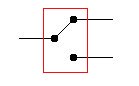
Figure 3: a three-way switch.
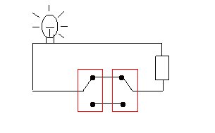
Figure 4: wiring two switches to one bulb.
| Switch 1 | 1 | 1 | 0 | 0 |
| Switch 2 | 1 | 0 | 1 | 0 |
| Light | 1 | 0 | 0 | 1 |
An infinite story house
And what if you live in a three story house and want to have three switches for the light in the hall? For this you need two three-way switches and one four-way switch, which is shown in figure 5. You arrange the three switches in a row, with the four-way switch in the middle, as in figure 6. As before, we write "0" for "the three-way switch is pointing downward" and "1" for "the three-way switch is pointing upward". There are now eight different possibilities for the arrangement of the switches.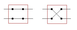
Figure 5: the left-hand position of the switch is 0 and the right-hand position is 1.
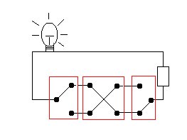
Figure 6: wiring three switches to a bulb. Switches 1 and 2 are in position 1 and switch 3 is in position 0. The switches' values add up to an even number and the light is on.
As you can see in figure 6, the light is on when two or none of the three switches are in position 1. To put it in the language of logic, the statement "the light is on" is true exactly when the statement "the switch is in position 1" is true for two of the switches, or for none of the switches. It is true precisely when the values for the three switches add up to an even number. If we write
"A" for the statement "switch 1 is in position 1", "B" for "switch 2 is in position 1" and "C" for "switch 3 is in position 1", then the light is on precisely when the statement
(A AND B AND NOT C) OR (A AND NOT B AND C) OR (NOT A AND B AND C) OR (NOT A AND NOT B AND NOT C)
is true.
| Switch 1 | 1 | 1 | 1 | 1 | 0 | 0 | 0 | 0 |
| Switch 2 | 1 | 1 | 0 | 0 | 1 | 1 | 0 | 0 |
| Switch 3 | 1 | 0 | 1 | 0 | 1 | 0 | 1 | 0 |
| Light | 0 | 1 | 1 | 0 | 1 | 0 | 0 | 1 |
And the good thing about all this is that it will work for any number of switches. No matter how tall your house is, the same principles will apply: the light will come on whenever the values of the different switches add up to an even number, and you can wire up the switches using a circuit with three-way switches at each end and four-way switches in the middle. The process works all the way up to infinity.
About the author

Yutaka Nishiyama is a professor at Osaka University of Economics, Japan. After studying mathematics at the University of Kyoto he went on to work for IBM Japan for 14 years. He is interested in the mathematics that occurs in daily life, and has written seven books about the subject. The most recent one, called "The mystery of five in nature", investigates, amongst other things, why many flowers have five petals. Professor Nishiyama is currently visiting the University of Cambridge.